• Advertisement

Kohler CV20S Wiring

Use this forum to discuss small engines, and the equipment or machinery that they power. This is the main section for any technical help posts and related questions.

Kohler CV20S Wiring

Postby JonCraig » Tue Mar 25, 2014 12:22 pm

So my father in law have me a Kohler CV20S that has relatively low hours; he upgraded to a larger motor. It sat for ~9 months, and now I'm trying to get it going again to (hopefully) sell. Problem is I'm not sure entirely how to wire it up on the bench to demonstrate to a buyer that it still runs.

Below you'll see the wiring harness. I've made it as far as hooking up the starter main, as well as the solenoid wire (this one to a pushbutton switch). I can get it to hit on starter fluid and run for a second or two, but I can't tell if its failure to continue to run is due to my still needing to hook up a wire, or if it just needs a carb rebuild.

Below are a couple pics. Basically if anyone would be kind enough to help me figure out what needs to be connected when to get the motor to run, I'd be very thankful. Thanks in advance!

Image

Image

Image

Image

Image
User avatar
JonCraig
Forum Regular
 
Posts: 81
Joined: Sun Nov 10, 2013 10:35 am

Advertisement

Re: Kohler CV20S Wiring

Postby KE4AVB » Tue Mar 25, 2014 12:41 pm

Kohler CV20-65541 was made for the Magic Circle OEM group. It has a 15/20 alternator with a fixed CDI ignition system.

The following it link to the service manual download on http://www.kohlerplus.com website. Login as guest after accepting terms. Note: this site require Internet Explorer or emulator to access. The wiring diagram for the Fixed CDI with 15/20 alternator is on page 34.

Note: The white wire is the kill wire "DO NOT" connect 12 volts to it or you will destroy your ignition coils. In the wiring diagram the the aqua blue ( lighter blue) is listed as Blue/Red. The only thing that need 12v is the fuel solenoid other than starter circuit which you have already connected for the engine to run.
The truest measure of society is the how it treats its elderly, its pets, and its prisoners.
User avatar
KE4AVB
Forum Pro
 
Posts: 6010
Joined: Mon Nov 04, 2013 11:23 am
Location: TorLand

Re: Kohler CV20S Wiring

Postby Deere2me » Tue Mar 25, 2014 1:31 pm

Or, if ya don't wanna jump thru hoops, go here : http://www.kohlerengines.com/manuals/landing.htm
The manual will have all the engine wiring diagrams.
http://ppeten.com/forums/viewtopic.php?f=4&t=836

I quote:
"Don't pay any attention to old Dummy."- okie
"pompous a**hole"- steinuit13
"I agree, Deere is a negative around here to say the least"-mek a nik
Nice, huh?
User avatar
Deere2me
Forum Pro
 
Posts: 439
Joined: Wed Jan 01, 2014 2:27 pm
Location: Chesapeake, VA

Re: Kohler CV20S Wiring

Postby JonCraig » Fri Mar 28, 2014 10:01 am

Thanks SO much for the links, guys. I'm looking at the wiring diagram, and I still can't quite figure this out.

Did I mention that I'm doing all this on the bench, with my own individual switches and not a proper keyswitch/ignition switch?

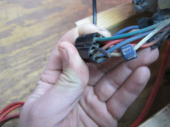
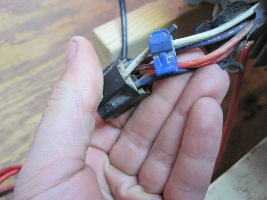
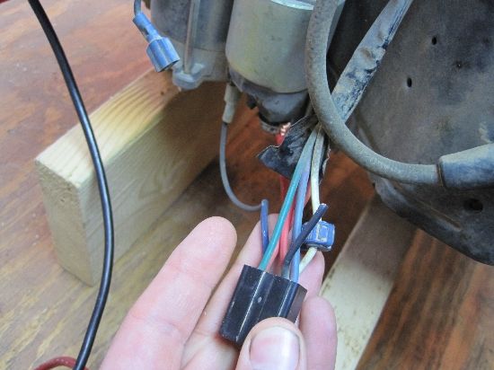
There are two red wires going into the wiring harness (marked "V" on page 34 of the service manual). I have my starter switch connected to the part of the harness that has TWO wires going into it. (That is to say, the factory Kohler harness has two wires going into the engine side of the connector.) One of them is the starter solenoid wire, marked "P" in the wiring diagram. The other is the "V" red wire. That (apparently) supplies +12V to the fuel solenoid (carb cutoff anti-backfire thing, if it's the same on Kohler as it is on the Briggs I'm used to).

One of the things I can't figure out is this… if that "V" red wire always has 12V applied to it, wouldn't that make the starter solenoid always hot, and thus constantly engage the starter? (Obviously that cannot be the case…).

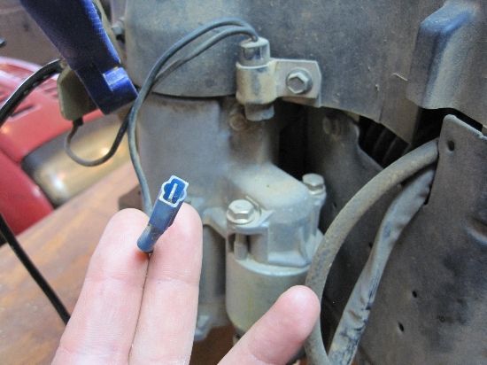
I think my other question is related… There are two terminals on the starter… on one I have my large (6 gauge or so) cable from the batt + going to the starter. In the wiring diagram, that seems to be where the +12 from the regulator (marked "K"), along with one of the "V" wires, connects as well. (that connection goes through fuse "O" in the diagram, if it helps orient you.)

There ARE two marks in the jumble of colors coming out from the harness connector on the diagram, and they look like they MIGHT be diodes… and if they are, I think that makes some of this logic make sense, as I try to work through that thusly:

So if part "O" is connected to batt positive via being connected to that starter lug, that feeds thru the harness to the ignition switch. When the operator turns the switch to start, the switch sends +12 down the blue wire to the starter solenoid (simple enough), as well as down the top "V" wire to turn on the fuel solenoid. Once the motor is running, the operator lets go of the momentary start switch, which disengages the "P" (starter solenoid) wire, and instantly engages the lowest "V" red wire, which continues supplying +12 to the fuel solenoid. The diodes are in place to prevent exactly what I was talking about before--eliminating the +12V from constantly hitting the starter solenoid & engaging the starter.

SOOOO… if anyone was actually kind enough to follow through all that, does that make sense, or am I reading this totally wrong?

Almost forgot… so simply grounding "U" (which is also connected to "D" grrrr….) is the proper way to kill the ignition, yes?

Thanks in advance for helping me brush the cobwebs off my electronics minor back in college days!

--JC
User avatar
JonCraig
Forum Regular
 
Posts: 81
Joined: Sun Nov 10, 2013 10:35 am

Re: Kohler CV20S Wiring

Postby bgsengine » Fri Mar 28, 2014 10:48 am

JonCraig wrote:One of the things I can't figure out is this… if that "V" red wire always has 12V applied to it, wouldn't that make the starter solenoid always hot, and thus constantly engage the starter? (Obviously that cannot be the case…).
It is a simple voltage drop trick (Notice the diode in the circuit according to wiring diagram?) - If you understand how voltage drops work, then it may be easier to wrap your brain around that circuit. :) the other part of the circuit feeds voltage to the fuel solenoid and SAM module - It is an interesting set up, but yes that circuit takes a 12V all the time but the solenoid does not engage until it has the full 12v to it (the other circuits draw down the voltage before it gets to the solenoid, until the "start" circuit is energized.)
How poor are they who have not patience. What wound did ever heal, but by degrees? - Iago (Othello Act II, Scene 3)
bgsengine
Briggs MST
Briggs MST
 
Posts: 3306
Joined: Sun Nov 03, 2013 10:07 pm
Location: Northcentral P.A.

Re: Kohler CV20S Wiring

Postby KE4AVB » Fri Mar 28, 2014 11:47 am

EDIT: Please Dis-regard this post. Reasons explain farther down this thread. I didn't see the steering diodes.

Brian better go get that second cup coffee this morning. :lol:

bgsengine wrote:
JonCraig wrote:One of the things I can't figure out is this… if that "V" red wire always has 12V applied to it, wouldn't that make the starter solenoid always hot, and thus constantly engage the starter? (Obviously that cannot be the case…).
It is a simple voltage drop trick (Notice the diode in the circuit according to wiring diagram?) - If you understand how voltage drops work, then it may be easier to wrap your brain around that circuit. :) the other part of the circuit feeds voltage to the fuel solenoid and SAM module - It is an interesting set up, but yes that circuit takes a 12V all the time but the solenoid does not engage until it has the full 12v to it (the other circuits draw down the voltage before it gets to the solenoid, until the "start" circuit is energized.)


:shock:
First this spec engine has the fixed CDI ignition system no SAM.

It is a regular starter solenoid setup. It is nothing but a high power relay. The terminal with the 6 ga, the red with fuse and violet from the volage regulator wires is hot all the time with full 12volts; just like most light switches your home. Nothing is applied to the starter motor until 12 volts is applied to small terminal which has the blue wire. Then the solenoid pulls in the contacts (here represented as copper bar, exactly a disc in the real starter solenoid) to supply the require voltage to starter motor. See diagram below that my help explain this better. The jumper in the just shows how you can bypass the ignition switch for starting and is only needed until the engine starts then it is disconnected.

Image
Last edited by KE4AVB on Fri Mar 28, 2014 2:08 pm, edited 1 time in total.
The truest measure of society is the how it treats its elderly, its pets, and its prisoners.
User avatar
KE4AVB
Forum Pro
 
Posts: 6010
Joined: Mon Nov 04, 2013 11:23 am
Location: TorLand

Re: Kohler CV20S Wiring

Postby bgsengine » Fri Mar 28, 2014 12:40 pm

KE4AVB wrote:Brian better go get that second cup coffee this morning. :lol:

bgsengine wrote:
JonCraig wrote:One of the things I can't figure out is this… if that "V" red wire always has 12V applied to it, wouldn't that make the starter solenoid always hot, and thus constantly engage the starter? (Obviously that cannot be the case…).
It is a simple voltage drop trick (Notice the diode in the circuit according to wiring diagram?) - If you understand how voltage drops work, then it may be easier to wrap your brain around that circuit. :) the other part of the circuit feeds voltage to the fuel solenoid and SAM module - It is an interesting set up, but yes that circuit takes a 12V all the time but the solenoid does not engage until it has the full 12v to it (the other circuits draw down the voltage before it gets to the solenoid, until the "start" circuit is energized.)


:shock:
First this spec engine has the fixed CDI ignition system no SAM.

It is a regular starter solenoid setup. It is nothing but a high power relay. The terminal with the 6 ga, the red with fuse and violet from the volage regulator wires is hot all the time with full 12volts; just like most light switches your home. Nothing is applied to the starter motor until 12 volts is applied to small terminal which has the blue wire. Then the solenoid pulls in the contacts (here represented as copper bar, exactly a disc in the real starter solenoid) to supply the require voltage to starter motor. See diagram below that my help explain this better. The jumper in the just shows how you can bypass the ignition switch for starting and is only needed until the engine starts then it is disconnected.

Image


Was not answering his wiring problem question - was answering his "how can that work" question - hence, the quoted portion of his post. :)
How poor are they who have not patience. What wound did ever heal, but by degrees? - Iago (Othello Act II, Scene 3)
bgsengine
Briggs MST
Briggs MST
 
Posts: 3306
Joined: Sun Nov 03, 2013 10:07 pm
Location: Northcentral P.A.

Re: Kohler CV20S Wiring

Postby Deere2me » Fri Mar 28, 2014 12:59 pm

JonCraig wrote:
There ARE two marks in the jumble of colors coming out from the harness connector on the diagram, and they look like they MIGHT be diodes… and if they are, I think that makes some of this logic make sense, as I try to work through that thusly:

So if part "O" is connected to batt positive via being connected to that starter lug, that feeds thru the harness to the ignition switch. When the operator turns the switch to start, the switch sends +12 down the blue wire to the starter solenoid (simple enough), as well as down the top "V" wire to turn on the fuel solenoid. Once the motor is running, the operator lets go of the momentary start switch, which disengages the "P" (starter solenoid) wire, and instantly engages the lowest "V" red wire, which continues supplying +12 to the fuel solenoid. The diodes are in place to prevent exactly what I was talking about before--eliminating the +12V from constantly hitting the starter solenoid & engaging the starter.


BINGO!!
http://ppeten.com/forums/viewtopic.php?f=4&t=836

I quote:
"Don't pay any attention to old Dummy."- okie
"pompous a**hole"- steinuit13
"I agree, Deere is a negative around here to say the least"-mek a nik
Nice, huh?
User avatar
Deere2me
Forum Pro
 
Posts: 439
Joined: Wed Jan 01, 2014 2:27 pm
Location: Chesapeake, VA

Re: Kohler CV20S Wiring

Postby KE4AVB » Fri Mar 28, 2014 2:05 pm

:bricks: Thanks Brian, I see where I missed the try in points. I had to blow the image to 200% for me to see them. I now see there are two steering diodes in wiring near the switch.

Jon sorry for the mis-information. My eyes are not what they once were.

Now I the one needs that pot of coffee and a kick in the seat of the pants for such a rookie electronics mistake. :lol:
The truest measure of society is the how it treats its elderly, its pets, and its prisoners.
User avatar
KE4AVB
Forum Pro
 
Posts: 6010
Joined: Mon Nov 04, 2013 11:23 am
Location: TorLand

Re: Kohler CV20S Wiring

Postby JonCraig » Fri Mar 28, 2014 9:06 pm

Thanks again, guys. It never ceases to amaze me what a wealth of knowledge this forum has. And as an obvious layman hobbyist, I'm very thankful that you pros are willing to take the time to help us newbies! If we ever meet in real life, I owe lots of you several beers. :D
User avatar
JonCraig
Forum Regular
 
Posts: 81
Joined: Sun Nov 10, 2013 10:35 am

Next

Return to Technical Discussion Forum

Who is online

Users browsing this forum: No registered users and 3 guests